
Introduction
In this tutorial, we are going to learn 74hc595 shift register working & interfacing with Arduino. The 74HC595 shift register is an essential component in digital electronics and microcontroller projects. It allows you to expand the number of outputs using only a few pins on your microcontroller, such as an Arduino. In this article, we will explore the working principle of the 74HC595 shift register and learn how to interface it with an Arduino.
Hardware Required
| Components | # | Buy From Amazon |
|---|---|---|
| Arduino UNO | 1 | Buy Now |
| 74HC595 shift register | 1 | Buy Now |
| LEDs 5mm | 8 | Buy Now |
| Resistors 220Ω | 8 | Buy Now |
| Jumper Wires | Few | Buy Now |
| Breadboard | 1 | Buy Now |
What is a Shift Register?
A shift register is a sequential logic circuit that can store and shift data. It consists of a chain of flip-flops connecting in series, allowing data to be shifted from one flip-flop to another. There are several types of shift registers, including Serial-in, Parallel-out (SIPO), Serial-out, Parallel-in (SOPI), Serial-in, Serial-out (SISO), and Parallel-in, Serial-out (PISO).
Understanding the 74HC595 Shift Register
The 74HC595 is a popular 8-bit shift register commonly uses in digital electronics projects. It has a compact 16-pin package and offers a wide range of applications. Let’s delve deeper into its pin configuration and working principle.
Working Principle
The 74HC595 operates by shifting data from the SER pin into the shift register when the SRCLK signal rises. Once the data is shifted, it remains stored in the register until the RCLK signal rises, causing the stored data to appear on the output pins. This mechanism allows you to control multiple outputs using a single microcontroller pin.
Features of 74HC595 Shift Register
- Serial-in, Parallel-out Operation: The 74HC595 shift register receives data in a serial manner, allowing you to input data one bit at a time. The data is then store internally and can be output simultaneously in parallel form.
- Cascade Capability: Multiple 74HC595 shift registers can be cascaded together, enabling you to expand the number of output pins without requiring additional microcontroller pins. This feature makes it useful for applications that require control of a large number of output devices.
- Wide Operating Voltage Range: The 74HC595 can operate within a wide voltage range, typically from 2V to 6V, making it compatible with a variety of digital systems and microcontrollers.
- High-Speed Operation: The 74HC595 is designing for high-speed operation, allowing for fast data transfer and output capabilities.
- Output Latch Control: The shift register has a latch pin (ST_CP) that enables you to control when the output values are updated. This latch functionality ensures that all the output pins change simultaneously, reducing potential glitches during updates.
- Shift Register Clock Input: The shift register has a clock input (SH_CP) that triggers the shifting of data from the serial input to the internal storage registers.
- Serial Data Input: The shift register has a serial data input pin (DS) where you can input data bit by bit in a sequential manner.
- Serial Data Output: The 74HC595 also provides a serial data output (Q7S) pin, allowing you to cascade multiple shift registers together.
- Clear Input: The shift register has a clear input (MR) that usees to clear the internal storage registers and reset the output pins to a known state.
- Low Power Consumption: The 74HC595 shift register is design to operate with low power consumption, making it suitable for battery-powered applications or power-sensitive projects.
Pinout of 74HC595 Shift Register
Pin Configuration
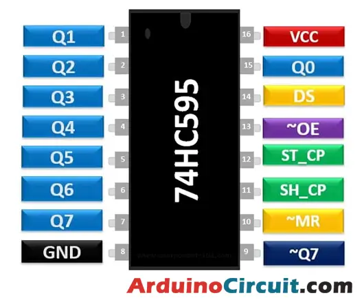
The 74HC595 shift register has 16 pins, each serving a specific purpose. The key pins are:
- SER (Serial Data Input): This pin receives the data to be shifted into the register.
- SRCLK (Shift Register Clock): This clock input synchronizes the shifting of data.
- RCLK (Register Clock): This clock input controls the storage of shifted data in the register.
- OE (Output Enable): When enabled, it allows the output data to appear on the output pins.
- Q0-Q7 (Output Pins): These pins are the parallel output pins, where the shifted data appears.
Pin Configuration
| Pin Number | Pin Name | Description |
| 1,2,3,4,5,6,7 | Output Pins (Q1 to Q7) | The 74hc595 has 8 output pins out of which 7 are these pins. They can be controlled serially |
| 8 | Ground | Connected to the Ground of the circuit |
| 9 | (Q7) Serial Output | This pin is used to connect more than one 74hc595 as cascading |
| 10 | (MR) Master Reset | Resets all outputs as low. Must be held high for normal operation |
| 11 | (SH_CP) Clock | This is the clock pin to which the clock signal has to be provided from MCU/MPU |
| 12 | (ST_CP) Latch | The Latch pin is used to update the data to the output pins. It is active high |
| 13 | (OE) Output Enable | The Output Enable is used to turn off the outputs. Must be held low for normal operation |
| 14 | (DS) Serial Data | This is the pin to which data is sent, based on which the 8 outputs are controlled |
| 15 | (Q0) Output | The first output pin. |
| 16 | Vcc | This pin powers the IC, typically +5V is used. |
How to Interface 74HC595 with Arduino
To interface the 74HC595 shift register with an Arduino, you will need a few components and follow a simple connection diagram. Let’s walk through the process.
Connection Diagram
- Connect the VCC pin of the 74HC595 to the 5V pin on the Arduino.
- Connect the GND pin of the 74HC595 to the GND pin on the Arduino.
- Connect the SER pin of the 74HC595 to any digital pin on the Arduino.
- Connect the SRCLK pin of the 74HC595 to another digital pin on the Arduino.
- Connect the RCLK pin of the 74HC595 to a third digital pin on the Arduino.
- Connect the OE pin of the 74HC595 to GND to enable the output.
- Connect the Q0-Q7 output pins of the 74HC595 to the appropriate resistors and LEDs.
Circuit Diagram

Installing Arduino IDE Software
First, you will require to Download the updated version of Arduino IDE Software and Install it on your PC or laptop. if you Learn How to install the Arduino step-by-step guide then click on how to install Arduino Button given Blow
Installing Libraries
Now when you are Ready to upload the code, to the Arduino Board you will need first to add the Following Libraries in Arduino, If you Learn How to add the library in the Arduino step-by-step guide click on how to install the library Button given Blow
Code Example
Once the connections are made, you can control the LEDs connected to the 74HC595 using Arduino code. Here’s a simple code example that shifts a binary pattern through the shift register and displays it on the LEDs:
//For more Projects: www.arduinocircuit.com

#include <SPI.h>

int SER_Pin = 4; // Serial Data Input pin
int SRCLK_Pin = 5; // Shift Register Clock pin
int RCLK_Pin = 6; // Register Clock pin

void setup() {
  pinMode(SER_Pin, OUTPUT);
  pinMode(SRCLK_Pin, OUTPUT);
  pinMode(RCLK_Pin, OUTPUT);
}

void loop() {
  // Shift in a binary pattern
  shiftOut(SER_Pin, SRCLK_Pin, MSBFIRST, B10101010);

  // Latch the shifted data to the output pins
  digitalWrite(RCLK_Pin, HIGH);
  delay(1000); // Pause for 1 second

  // Shift in a different pattern
  shiftOut(SER_Pin, SRCLK_Pin, MSBFIRST, B01010101);

  // Latch the shifted data to the output pins
  digitalWrite(RCLK_Pin, HIGH);
  delay(1000); // Pause for 1 second
}
In this code example, the shiftOut() function is used to shift the binary pattern into the shift register, and then the digitalWrite() function is used to latch the data to the output pins. The pattern is shifted out and displayed on the LEDs connected to the 74HC595.
Advantages and Applications
The 74HC595 shift register offers several advantages and finds applications in various projects, including:
- Increased output capability: It allows expanding the number of outputs using fewer microcontroller pins.
- Reduced pin usage: It frees up microcontroller pins for other purposes.
- Simplified wiring: It simplifies the wiring complexity by using serial communication.
- LED matrix control: It uses to control large LED matrices efficiently.
- Multiplexing: It enables multiplexing multiple displays or devices using a minimal number of pins.
Conclusion
The 74HC595 shift register is a versatile component that allows expanding the output capability of microcontrollers, such as Arduino. By understanding its working principle and following the proper interfacing techniques, you can enhance your project’s capabilities and reduce pin usage. Experimenting with the shift register opens up possibilities for controlling multiple devices with ease.
FAQs (Frequently Asked Questions)
- Q: Can I cascade multiple 74HC595 shift registers?
- Ans: Yes, you can cascade multiple 74HC595 shift registers to expand the number of outputs even further. Each additional shift register requires a serial connection to the previous one.
- Q: What is the maximum number of outputs I can achieve with the 74HC595?
- Ans: Theoretically, you can control up to 256 outputs with cascaded 74HC595 shift registers. However, practical limitations, such as current sourcing capabilities, should be considered.
- Q: Can I use the 74HC595 to read input signals?
- Ans: No, the 74HC595 is a shift register designed for output purposes only. It does not have the capability to read input signals.
- Q: Are there alternative shift registers I can use besides the 74HC595?
- Ans: Yes, there are other shift registers available, such as the CD4021, which is an 8-bit parallel-in, serial-out (PISO) shift register. Choose the one that best suits your project requirements.


