Introduction
Hello and welcome to this tutorial on How to program ATtiny85 with Arduino UNO Easy way. If you’re on the lookout for a cost-effective yet powerful microcontroller, the ATtiny85 is an excellent choice. In this guide, we’ll walk through the process step by step, using two examples to illustrate the programming procedure. Let’s dive in!
Hardware Required
You will require the following Hardware Components for How to program ATtiny85 with Arduino UNO Easy way.
| Components | # | Buy From Amazon |
|---|---|---|
| Arduino UNO | 1 | Buy Link |
| ATtiny85 Microcontroller | 1 | Buy Link |
| LED 5mm | 5 | Buy Link |
| Resistors 180Ω | 5 | Buy Link |
| Capacitor 10uF | 1 | Buy Link |
| Jumper Wires | Few | Buy Link |
| Breadboard | 1 | Buy Link |
| 5v Battery | 1 | Buy Link |
What is ATtiny85?
The ATtiny85 is a powerful yet compact microcontroller that opens up a world of possibilities for your DIY projects. Despite its small size, it packs quite a punch, making it a popular choice among hobbyists and professionals alike.
Pinout
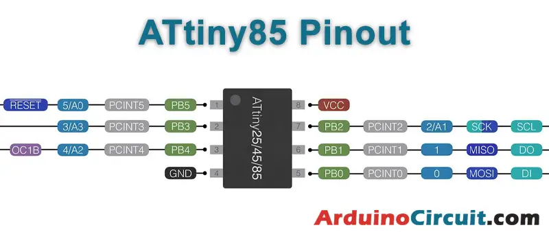
Pin Configuration of Attiny85
It is an 8-pin IC as shown in the Atiny85 pin diagram shown above. Most I/O pins of the chip have more than one function and the description for each pin is given below.
| Pin no. | Pin Name | Description | Secondary Function |
|---|---|---|---|
| 1 | PB5 (PCINT5/ADC0/dW) | Pin5 of PORTB | PCINT5: Pin Change Interrupt 0, Source5 RESET : Reset Pin ADC0: ADC Input Channel 0 dW : debug WIRE I/O |
| 2 | PB3 (PCINT3/XTAL1/CLKI/ADC3) | Pin3 of PORTB | PCINT3: Pin Change Interrupt 0, Source3 XTAL1 : Crystal Oscillator Pin1 CLKI: External Clock Input OC1B : Complementary Timer/Counter1 Compare Match B Output ADC3: ADC Input Channel 3 |
| 3 | PB4 (PCINT4/XTAL2/CLKO/OC1B/ADC2) | Pin4 of PORTB | PCINT3: Pin Change Interrupt 0, Source3 XTAL1 : Crystal Oscillator Pin1 CLKI: External Clock Input OC1B : Complementary Timer/Counter1 Compare Match B Output ADC3: ADC Input Channel 3 |
| 4 | GND | Connected to Ground | |
| 5 | PB0(MOSI/DI/SDA/AIN0/OC0A/AREF/ PCINT0) | Pin0 of PORTB | MOSI: SPI Master Data Output / Slave Data Input DI: USI Data Input (Three Wire Mode) SDA: USI Data Input (Two Wire Mode) AIN0: Analog Comparator, Positive Input OC0A : Timer/Counter0 Compare Match A output : Complementary Timer/Counter1 Compare Match A Output AREF: External Analog Reference PCINT0: Pin Change Interrupt 0, Source 0 |
| 6 | PB1(MISO/D0/AIN1/OC0B/OC1A/ PCINT1) | Pin1 of PORTB | PCINT4 : Pin Change Interrupt 0, Source 4 XTAL2 : Crystal Oscillator Pin 2 CLKO : System Clock Output OC1B: Timer/Counter1 Compare Match B Output ADC2: ADC Input Channel 2 |
| 7 | PB2(SCK/USCK/SCL/ADC1/T0/INT0/ PCINT2) | Pin2 of PORTB | MISO: SPI Master Data Input / Slave Data Output DO : USI Data Output (Three Wire Mode) AIN1: Analog Comparator, Negative Input OC0B : Timer/Counter0 Compare Match B Output OC1A: Timer/Counter1 Compare Match A Output PCINT1: Pin Change Interrupt 0, Source 1 |
| 8 | VCC | SCK: Serial Clock Input USCK : USI Clock (Three Wire Mode) SCL : USI Clock (Two Wire Mode) ADC1 : ADC Input Channel 1 T0 : Timer/Counter0 Clock Source INT0: External Interrupt 0 Input PCINT2: Pin Change Interrupt 0, Source 2 |
Features and Electrical Characteristics
| CPU | 8 bit |
| Number of Pins | 8 |
| Number of Programmable I/O pins | 6 |
| Operating Voltage | +1.8 V to +5.5V (ATTINY85V)+2.7 V to +5.5V (ATTINY85)(+6.0V being absolute maximum supply voltage) |
| Maximum DC Current per I/O Pin | 40 mA |
| Maximum DC Current through VCC and GND Pins | 200 mA |
| Operating Temperature | -55ºC to +125ºC |
| Communication Interface | Master/Slave SPI Serial Interface(5,6,7 PINS) [Can be used for programming this controller]I2C or Two-wire Serial Interface(5,7 PINS)[Can be used to connect peripheral devices and sensors]Universal Serial Interface (5,6,7 PINS) [Can be used for communicating with other controllers] |
| UART Interface | Not available |
| ADC Feature | 4channels, 10-bit resolution ADC |
| Analog Comparators | 1 |
| Timer Module | Two 8-bit counter |
| PWM outputs | 4 |
| External Oscillator | 0-10MHz for ATTINY85V0-20MHz for ATTINY85 |
| Internal Oscillator | 0-8MHz Calibrated Internal R-C Oscillator |
| CPU Speed | 1 MIPS@1MHz |
| Program Memory or Flash memory size | 8Kbytes[10000 write/erase cycles] |
| RAM size | 512Bytes on Internal SRAM |
| EEPROM size | 512Bytes of In-System Programmable EEPROM |
| Program Lock | Available |
| Watchdog Timer | Available |
| Power Save Modes | Three Modes[Idle, ADC Noise Reduction, Power-down] |
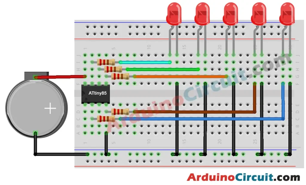
Circuit Diagram
The following circuit shows you the connection of How to program ATtiny85 with Arduino UNO Easy way Please make the connection carefully
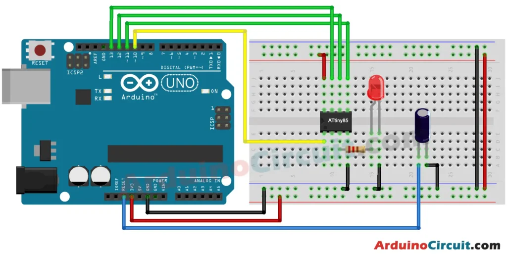
Working Explanation
The ATtiny85 communicates with the Arduino UNO through a process called “Arduino as ISP” (In-System Programmer). This essentially turns your Arduino UNO into a programmer for the ATtiny85. By uploading a specific sketch to your Arduino UNO, you can then transfer your code to the ATtiny85 microcontroller, allowing it to perform various tasks.
Installing Arduino IDE Software
First, you will require to Download the updated version of Arduino IDE Software and Install it on your PC or laptop. if you Learn How to install the Arduino step-by-step guide then click on how to install Arduino Button given Blow
Code
//For more Projects: www.arduinocircuit.com

void setup() {
  pinMode(0, OUTPUT);

}
void loop() {
  digitalWrite(0, HIGH);
  delay(500);
  digitalWrite(0, LOW);
  delay(500);
}
Let’s Test the Circuit
Applications
- LED Blinking Patterns: Utilize the GPIO pins to create captivating LED blinking patterns. The compact size of the ATtiny85 makes it perfect for crafting small, attention-grabbing displays.
- Sensor Node for IoT: Leverage its ADC channels to turn the ATtiny85 into a sensor node for your Internet of Things (IoT) projects. Monitor environmental variables and send data to your central system.
- Sound and Music Projects: With PWM channels, you can create musical tunes or sound effects in your projects. Perfect for adding an auditory dimension to your creations.
- Low-Power Applications: The ATtiny85’s low power consumption makes it ideal for battery-operated projects. Design energy-efficient gadgets without compromising on functionality.
- Miniature Robotics: Drive small motors and control basic robotic movements using the GPIO pins. Build your own pocket-sized robots that can navigate through simple tasks.
Conclusion
Programming the ATtiny85 with your Arduino UNO opens up a world of possibilities, allowing you to create compact yet powerful projects. Experiment with the applications mentioned or let your imagination run wild to explore the full potential of this tiny but mighty microcontroller.