Introduction
Wireless communication is a cornerstone of modern electronics, enabling devices to exchange information without the constraints of physical connections. The RF433 MHz Transceiver Module offers a convenient way to transmit and receive analog data wirelessly. In this comprehensive guide, we will explore how to set up and use the RF433 transceiver to send and receive analog data between two Arduino Nano boards. Additionally, we will integrate a 16×2 LCD display, a potentiometer, and a red LED to visualize the transmitted data. By the end of this tutorial, you will have the knowledge and skills to How to Send Analog Data and Receive Data using RF433, enhancing your understanding of wireless technology and data exchange. So, let’s delve into the world of wireless communication with Arduino and unlock the potential of the RF433 MHz Transceiver Module!
Hardware Required
You will require the following Hardware Components for Interfacing RF 433MHz Transmitter/Receiver Module With Arduino.
| Components | # | Buy From Amazon |
|---|---|---|
| Arduino Nano | 1 | Buy Now |
| RF433 MHz Transceiver, Receiver Module | 1 | Buy Now |
| 16×2 LCD Display | 1 | Buy Now |
| Potentiometer | 1 | Buy Now |
| Red Led | 1 | Buy Now |
| 9v DC Adapter (Optional) | 1 | Buy Now |
| Jumper Wires | Few | Buy Now |
| Breadboard | 1 | Buy Now |
Components and Setup
To create this wireless communication system, you will need an Arduino Nano as both the transmitter and receiver. Connect a potentiometer to the transmitter’s analog input pin and configure the RF433 module for transmission. On the receiver side, connect the RF433 receiver module and set up the 16×2 LCD display to show the received analog data. By carefully wiring the components and programming both Arduinos, you will establish a wireless link for sending and receiving analog data.
Sending Analog Data
To send analog data wirelessly using the RF433 transceiver, we will use one Arduino Nano as the transmitter and another as the receiver. We will connect a potentiometer to the transmitter Arduino’s analog input pin to simulate an analog sensor. The analog reading from the potentiometer will be converted to a digital value and transmitted via the RF433 module. The receiver Arduino will decode the transmitted data and display it on a 16×2 LCD display. Additionally, a red LED will illuminate to indicate successful data transmission.
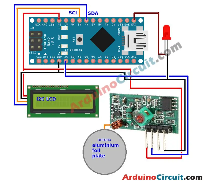
Circuit Diagram
The following circuit shows you. How 433 MHz RF Module Works & Interfacing with Arduino Please make the connection carefully

Receiving Analog Data
On the receiving end, the second Arduino Nano will use the RF433 receiver module to capture the transmitted data. The received data will be processed and displayed on the 16×2 LCD display, providing a real-time visualization of the analog reading. The red LED will also light up to indicate that data has been successfully received. This bidirectional communication demonstrates how the RF433 transceiver module facilitates wireless data exchange between devices.
Circuit Diagram
The following circuit shows you. How 433 MHz RF Module Works & Interfacing with Arduino Please make the connection carefully
Installing Arduino IDE Software
First, you will require to Download the updated version of Arduino IDE Software and Install it on your PC or laptop. if you Learn How to install the Arduino step-by-step guide then click on how to install Arduino Button given Blow
Installing Libraries
Now when you are Ready to upload the code, to the Arduino Board you will need first to add the Following Libraries in Arduino, If you Learn How to add the library in the Arduino step-by-step guide click on how to install the library Button given Blow
Code For Transmitter Module
//For more Projects: www.arduinocircuit.com

#include <VirtualWire.h>
#define txPowerPin 8
// LED’s
const int ledPin = 13;


// Sensors
const int Sensor1Pin = A2;
// const int Sensor2Pin = 3;

int Sensor1Data;
//int Sensor2Data;
char Sensor1CharMsg[4];

void setup() {
pinMode(txPowerPin, OUTPUT);
pinMode(txPowerPin, LOW);
// PinModes
// LED
pinMode(ledPin,OUTPUT);
// Sensor(s)
pinMode(Sensor1Pin,INPUT);

// for debugging
Serial.begin(9600);

// VirtualWire setup
vw_setup(2000); // Bits per sec
vw_set_tx_pin(12); // VirtualWire transmit pin
}

void loop() {
digitalWrite(txPowerPin, HIGH);
// Read and store Sensor 1 data
Sensor1Data = analogRead(Sensor1Pin);

// Convert integer data to Char array directly
itoa(Sensor1Data,Sensor1CharMsg,10);

// DEBUG
Serial.print(“Sensor1 Integer: “);
Serial.print(Sensor1Data);
Serial.print(” Sensor1 CharMsg: “);
Serial.print(Sensor1CharMsg);
Serial.println(” “);
delay(1000);

// END DEBUG

digitalWrite(13, true); // Turn on a light to show transmitting
vw_send((uint8_t *)Sensor1CharMsg, strlen(Sensor1CharMsg));
vw_wait_tx(); // Wait until the whole message is gone
digitalWrite(13, false); // Turn off a light after transmission
digitalWrite(txPowerPin, LOW);
delay(2000);

} // END void loop…
Code For Receiver Module
//For more Projects: www.arduinocircuit.com

#include <VirtualWire.h>
#define txPowerPin 8
// LED’s
const int ledPin = 13;


// Sensors
const int Sensor1Pin = A2;
// const int Sensor2Pin = 3;

int Sensor1Data;
//int Sensor2Data;
char Sensor1CharMsg[4];

void setup() {
pinMode(txPowerPin, OUTPUT);
pinMode(txPowerPin, LOW);
// PinModes
// LED
pinMode(ledPin,OUTPUT);
// Sensor(s)
pinMode(Sensor1Pin,INPUT);

// for debugging
Serial.begin(9600);

// VirtualWire setup
vw_setup(2000); // Bits per sec
vw_set_tx_pin(12); // VirtualWire transmit pin
}

void loop() {
digitalWrite(txPowerPin, HIGH);
// Read and store Sensor 1 data
Sensor1Data = analogRead(Sensor1Pin);

// Convert integer data to Char array directly
itoa(Sensor1Data,Sensor1CharMsg,10);

// DEBUG
Serial.print(“Sensor1 Integer: “);
Serial.print(Sensor1Data);
Serial.print(” Sensor1 CharMsg: “);
Serial.print(Sensor1CharMsg);
Serial.println(” “);
delay(1000);

// END DEBUG

digitalWrite(13, true); // Turn on a light to show transmitting
vw_send((uint8_t *)Sensor1CharMsg, strlen(Sensor1CharMsg));
vw_wait_tx(); // Wait until the whole message is gone
digitalWrite(13, false); // Turn off a light after transmission
digitalWrite(txPowerPin, LOW);
delay(2000);

} // END void loop…
Applications
- Wireless Remote Control: One of the most common applications of the 433 MHz RF module is in remote control systems. It’s used in devices like remote-controlled toys, home automation systems, and garage door openers. The transmitter can send control signals wirelessly to the receiver, allowing users to control devices from a distance.
- Wireless Data Transmission: These modules are utilized in various applications where wireless data transmission is required. This includes transmitting sensor data from remote locations to a central hub, ideal for environmental monitoring or industrial automation.
- Wireless Sensors Networks: The 433 MHz RF modules can be integrated into wireless sensor networks where multiple sensor nodes transmit data to a central node for processing. This setup is useful in industrial settings for monitoring various parameters.
- Home Automation: From controlling lights to adjusting thermostats, the RF module can be part of a home automation setup. This allows users to control and manage household devices remotely.
Conclusion
You have successfully learned how to use the RF433 MHz Transceiver Module to establish wireless communication between two Arduino Nano boards. By sending and receiving analog data, you have gained insights into wireless data exchange principles and real-time data visualization. This hands-on experience empowers you to explore further applications of wireless communication, from remote sensing to home automation. Armed with this knowledge, you can embark on new projects that leverage the capabilities of the RF433 transceiver and enhance your understanding of wireless technology. So, experiment and innovate with wireless communication, and let the RF433 transceiver open doors to exciting possibilities in the world of electronics.


