In this article, we will explore the Top 10 Arduino LED Projects for Beginners with Code. Each project comes with code examples that can be easily implemented and customized to enhance your understanding of Arduino programming and LED control.
Arduino is a popular open-source electronics platform that enables enthusiasts, hobbyists, and beginners to create a wide range of projects. One of the most common and exciting applications of Arduino is working with LEDs (Light Emitting Diodes). LEDs are versatile components that can be used to create various lighting effects and displays.
1: LED Blink and Flash with Arduino
Introduction
Hi, today we will start using the Arduino board: you will learn how to make a led flash in a pulsed and regular way. This is usually the first project that is made with Arduino UNO and is the basis for those who start programming it.
We can also use the integrated LED on the card indicated with the letter L without necessarily connecting the LED as per the diagram. The L led already has an integrated smd resistor on the board, this allows us to insert the led directly into the GND and 13 pins.
Click here For more information About LED Blink and Flash with Arduino and this is 1st Project of the Top 10 Arduino LED Projects for Beginners with code
Hardware Required
| Components | # | Buy From Amazon |
|---|---|---|
| Arduino UNO | 1 | Buy Now |
| LED 5mm | 1 | Buy Now |
| Resistor 220Ω | 1 | Buy Now |
| Jumper Wires | Few | Buy Now |
| Breadboard | 1 | Buy Now |
Circuit Diagram

Code
//For more Projects: www.arduinocircuit.com

  #define LED 13            // LED pin digitale 13

void setup() {
  pinMode(LED, OUTPUT);     // output
}

void loop() {
  digitalWrite(LED, HIGH);
  delay(1000);
  digitalWrite(LED, LOW);
  delay(1000);
}
2: Arduino Choice of LED Ignition with 2 Buttons
Introduction
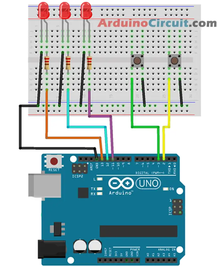
Arduino is a popular microcontroller-based platform used by hobbyists and professionals alike to create a wide range of electronic projects. In this project, we will demonstrate how to use an Arduino board to control an LED ignition circuit using two push buttons. This simple project is a great introduction to using Arduino and can be easily adapted for a wide range of applications.
We will not use the usual external Pull-Up resistors on the buttons but we will exploit the internal resistors of the ATmega328P microcontroller. The pull-up is used to prevent the electrical and electromagnetic interferences present in the environment, introduced thanks to the very high impedance of the input pins, from causing random and involuntary commutations, by leaving the pin disconnected (this would occur with open contacts).
Click here For more information About Arduino Choice of LED Ignition with 2 Buttons and this is 2nd Project of the Top 10 Arduino LED Projects for Beginners with code
Hardware Required
| Components | # | Buy From Amazon |
|---|---|---|
| Arduino UNO | 1 | Buy Now |
| LED 5mm (Red) | 3 | Buy Now |
| Resistors 220Ω | 3 | Buy Now |
| Buttons | 2 | Buy Now |
| Jumper Wires | Few | Buy Now |
| Breadboard | 1 | Buy Now |
Circuit Diagram
Code
//For more Projects: www.arduinocircuit.com
/* In this example we will show how to select
the LED to turn on with two Up and Down buttons */
// Pin definition
int led1 = 11;
int led2 = 12;
int led3 = 13;
int buttonUp = 2;
int buttonDown = 3;
// Definition of the variables
int led = 1; // led to turn on
void setup() {
  // Set pins as outputs
  pinMode (led1, OUTPUT);
  pinMode (led2, OUTPUT);
  pinMode (led3, OUTPUT);
  // Setting the pins as inputs
  pinMode(buttonUp, INPUT);
  pinMode (buttonDown, INPUT);
  // Enabling of the internal PullUp resistors on the inputs
  digitalWrite(buttonUp, HIGH);
  digitalWrite(buttonDown, HIGH);
}
void loop() {
  if (digitalRead (buttonUp) == 0){ // if the button is pressed
    led++; // Increment the led variable
    if (led>3) { // If the variable exceeds the value 3
      led=1; // Reset the variable to 1
    }
    delay(500); // Pause for debounce
  }
if (digitalRead (buttonDown) == 0){ // if the button is pressed
    led--; // Decrement the led variable
    if (led<1) { // If the variable is less than the value 1
      led=3; // Reset the variable to 3
    }
    delay(500); // Pause for debounce
   }
   if (led==1) {
    digitalWrite(led1, HIGH); // Turn on led1
    digitalWrite (led2, LOW); // Turn off led2
    digitalWrite (led3, LOW); // Turn off led3
   }
   if (led==2) {
    digitalWrite(led1, LOW); // Turn off led1
    digitalWrite(led2, HIGH); // Turn on led2
    digitalWrite (led3, LOW); // Turn off led3
   }
   if (led==3) {
    digitalWrite(led1, LOW); // Turn off led1
    digitalWrite (led2, LOW); // Turn off led2
    digitalWrite(led3, HIGH); // Turn on led3
   }
}
3: RGB Led Arduino Tutorial
Introduction
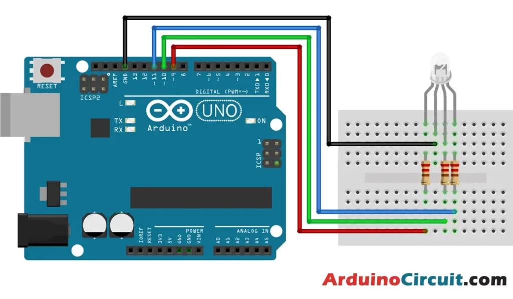
In this tutorial, we will walk through the steps to connect an RGB LED to an Arduino board, write the necessary code to control the LED, and create different colors and lighting effects. We will start with a basic example that cycles through different colors, and then move on to more advanced examples that allow you to set the color of the LED using values from 0 to 255 for each of the red, green, and blue channels.
Arduino is a popular open-source electronics platform that allows you to easily create interactive projects. With its easy-to-use programming environment, it is possible to control an RGB LED with an Arduino board, enabling you to create various lighting effects and color combinations.
Click here For more information About RGB Led Arduino Tutorial and this is 3rd Project of the Top 10 Arduino LED Projects for Beginners with code
Hardware Required
| Components | # | Buy From Amazon |
|---|---|---|
| Arduino UNO | 1 | Buy Now |
| RGB Led | 1 | Buy Now |
| Resistor 220Ω | 3 | Buy Now |
| Jumper Wires | Few | Buy Now |
| Breadboard | 1 | Buy Now |
Circuit Diagram
Code
//For more info Visits: www.arduinocircuit.com

int redPin = 9;
int greenPin = 10;
int bluePin = 11;

void setup() {
  pinMode(redPin, OUTPUT);
  pinMode(greenPin, OUTPUT);
  pinMode(bluePin, OUTPUT);
}

void loop() {
  // Set the LED to red
  setColor(255, 0, 0);
  delay(1000);

  // Set the LED to green
  setColor(0, 255, 0);
  delay(1000);

  // Set the LED to blue
  setColor(0, 0, 255);
  delay(1000);

  // Set the LED to yellow
  setColor(255, 255, 0);
  delay(1000);
}

void setColor(int red, int green, int blue) {
  analogWrite(redPin, red);
  analogWrite(greenPin, green);
  analogWrite(bluePin, blue);
}
4: Dual LED Chaser Arduino Project
Introduction
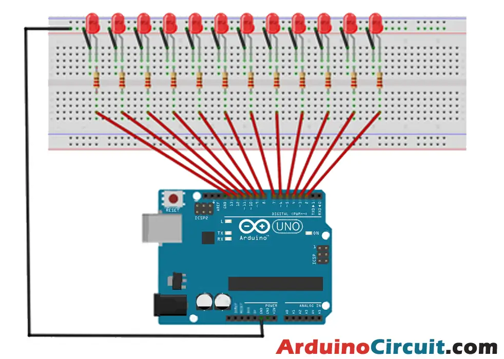
In This Project, we are going to make a Dual LED Chaser Arduino Circuit Project for Beginners. Basically, The Dual LED Chaser Arduino Project is an exciting electronics project that involves creating a circuit that flashes 12 LEDs in a chaser pattern. This project is an excellent way for beginners to learn about Arduino programming, electronics, and circuit design.
The circuit consists of an Arduino board, 12 LEDs, and 12 resistors with values between 220 ohms and 470 ohms. The LEDs are arranged in two rows, with each row containing six LEDs. The LEDs flash alternately, creating a dual-chaser effect.
Click here For more information About Dual LED Chaser Arduino Project and this is 4th Project of the Top 10 Arduino LED Projects for Beginners with code
Hardware Required
| Components | # | Buy From Amazon |
|---|---|---|
| Arduino UNO | 1 | Buy Now |
| LED 5mm | 12 | Buy Now |
| Resistors 220Ω to 470Ω | 12 | Buy Now |
| Jumper Wires | Few | Buy Now |
| Breadboard | 1 | Buy Now |
Circuit Diagram
Code
//For more Projects: www.arduinocircuit.com

// change speed of display here
#define SPEED_MS  100
void setup() {
  // set up pins 2 to 13 as outputs
  for (int i = 2; i <= 13; i++) {
    pinMode(i, OUTPUT);
  }
}
uint16_t chase2 = 13; // keeps track of second LED movement

void loop() {
  // move first LED from left to right and second from right to left
  for (int i = 2; i < 13; i++) {
    allLEDsOff();
    digitalWrite(i, HIGH);      // chaser 1
    digitalWrite(chase2, HIGH); // chaser 2
    chase2--;
    // stop LEDs from appearing to stand still in the middle
    if (chase2 != 7) {
      delay(SPEED_MS);
    }
  }
  // move first LED from right to left and second LED from left to right
  for (int i = 13; i > 2; i--) {
    allLEDsOff();
    digitalWrite(i, HIGH);      // chaser 1
    digitalWrite(chase2, HIGH); // chaser 2
    chase2++;
    // stop LEDs from appearing to stand still in the middle
    if (chase2 != 8) {
      delay(SPEED_MS);
    }
  }
}
// function to switch all LEDs off
void allLEDsOff(void)
{
  for (int i = 2; i <= 13; i++) {
    digitalWrite(i, LOW);
  }
}
5: Moving Light Display Arduino Project
Introduction
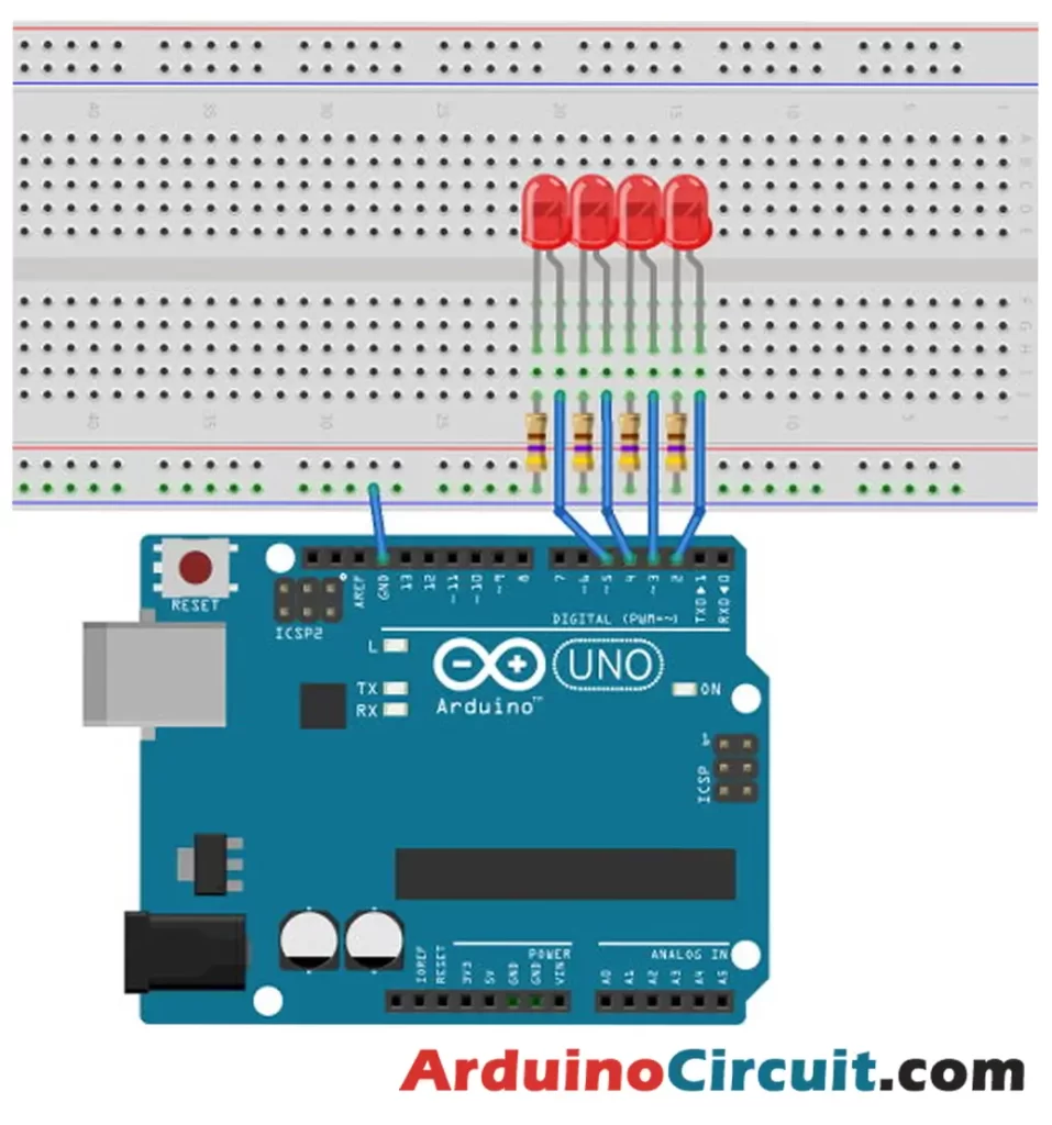
The Moving Light Display Arduino Project is an exciting project that involves creating a circuit that can display moving lights. This project is an excellent way for beginners to learn about Arduino programming, electronics, and circuit design.
The circuit consists of an Arduino board, four LEDs, and four resistors with values between 220 and 470 ohms. The LEDs are connected to the Arduino board in a specific pattern, which creates the moving light display.
Click here For more information About the Moving Light Display Arduino Project, this is 5th Project of the Top 10 Arduino LED Projects for Beginners with code
Hardware Required
| Components | # | Buy From Amazon |
|---|---|---|
| Arduino UNO | 1 | Buy Now |
| LED 5mm | 4 | Buy Now |
| Resistors 220Ω to 470Ω | 4 | Buy Now |
| Jumper Wires | Few | Buy Now |
| Breadboard | 1 | Buy Now |
Circuit Diagram
Code
//For more Projects: www.arduinocircuit.com
// change speed of pattern change in milliseconds here
#define SPEED_MS  300

// change LED patterns here
unsigned char led_pattern[] = {
  0x01, 0x02, 0x04, 0x08, 0x04, 0x02, 0x01, 0x00,
  0x06, 0x09, 0x06, 0x09, 0x06, 0x09, 0x06, 0x09,
  0x05, 0x0a, 0x05, 0x0a, 0x05, 0x0a, 0x05, 0x0a
};

void setup() {
  // set pin 2 to 5 as outputs
  for (int i = 2; i <= 5; i++) {
    pinMode(i, OUTPUT);
  }
}

void loop() {
  DisplayPattern(led_pattern, sizeof(led_pattern));
  delay(SPEED_MS);
}

void DisplayPattern(unsigned char *pattern, int num_patterns)
{
  static int pattern_num = 0; // keeps count of patterns
  unsigned char mask = 1;     // for testing each bit in pattern

  // do for LEDs on pin 2 to pin 5
  for (int i = 2; i <= 5; i++) {
    // check if bit in pattern is set or not and switch LED accordingly
    if (pattern[pattern_num] & mask) {
      digitalWrite(i, HIGH);
    }
    else {
      digitalWrite(i, LOW);
    }
    mask <<= 1;   // adjust mask for checking next bit in pattern
  }
  pattern_num++;  // move to next pattern for next function call
  // keep pattern within limits of pattern array
  if (pattern_num >= num_patterns) {
    pattern_num = 0;
  }
}
6: LED Brightness Control with Two Buttons
Introduction
In this tutorial, we will learn how to control the brightness of an LED with two buttons using an Arduino. The circuit includes two buttons – one for increasing the brightness and the other for decreasing the brightness of the LED. By pressing the appropriate button, we can adjust the brightness of the LED.
Click here For more information About LED Brightness Control with Two Buttons and this is the 6th Project of the Top 10 Arduino LED Projects for Beginners with code
Hardware Required
| Components | # | Buy From Amazon |
|---|---|---|
| Arduino UNO | 1 | Buy Now |
| LED 5mm | 1 | Buy Now |
| Buttons | 2 | Buy Now |
| Resistors 220Ω | 1 | Buy Now |
| Resistors 10KΩ | 2 | Buy Now |
| Jumper Wires | Few | Buy Now |
| Breadboard | 1 | Buy Now |
Circuit Diagram

Code
//For more Projects: www.arduinocircuit.com

const int ledPin = 9;
const int buttonPin1 = 12; // Increment Button
const int buttonPin2 = 13; // Decrement Button

int lastState1 = HIGH; // the previous state from the input pin
int lastState2 = HIGH;
int pushCounter = 0;  // counter for the number of button presses
int currentState1, currentState2;     // the current reading from the input pin
int fadeValue = 0;

void setup() {
  pinMode(ledPin, OUTPUT);
  pinMode(buttonPin1, INPUT);
  pinMode(buttonPin2, INPUT);
}

void loop() {
  currentState1 = digitalRead(buttonPin1);
  currentState2 = digitalRead(buttonPin2);
  if (currentState1 != lastState1) {
    if (currentState1 == LOW) {
      pushCounter++;
      fadeValue = pushCounter * 32;
    }
  }
  lastState1 = currentState1;

  if (currentState2 != lastState2) {
    if (currentState2 == LOW) {
      pushCounter--;
      fadeValue = pushCounter * 32;
    }
  }
  lastState2 = currentState2;

  analogWrite(ledPin, fadeValue);

  if (pushCounter >= 8) {
    pushCounter = 0;
  }
  delay(50);
}
7: LED with PCF8574 – Arduino Projects
Introduction
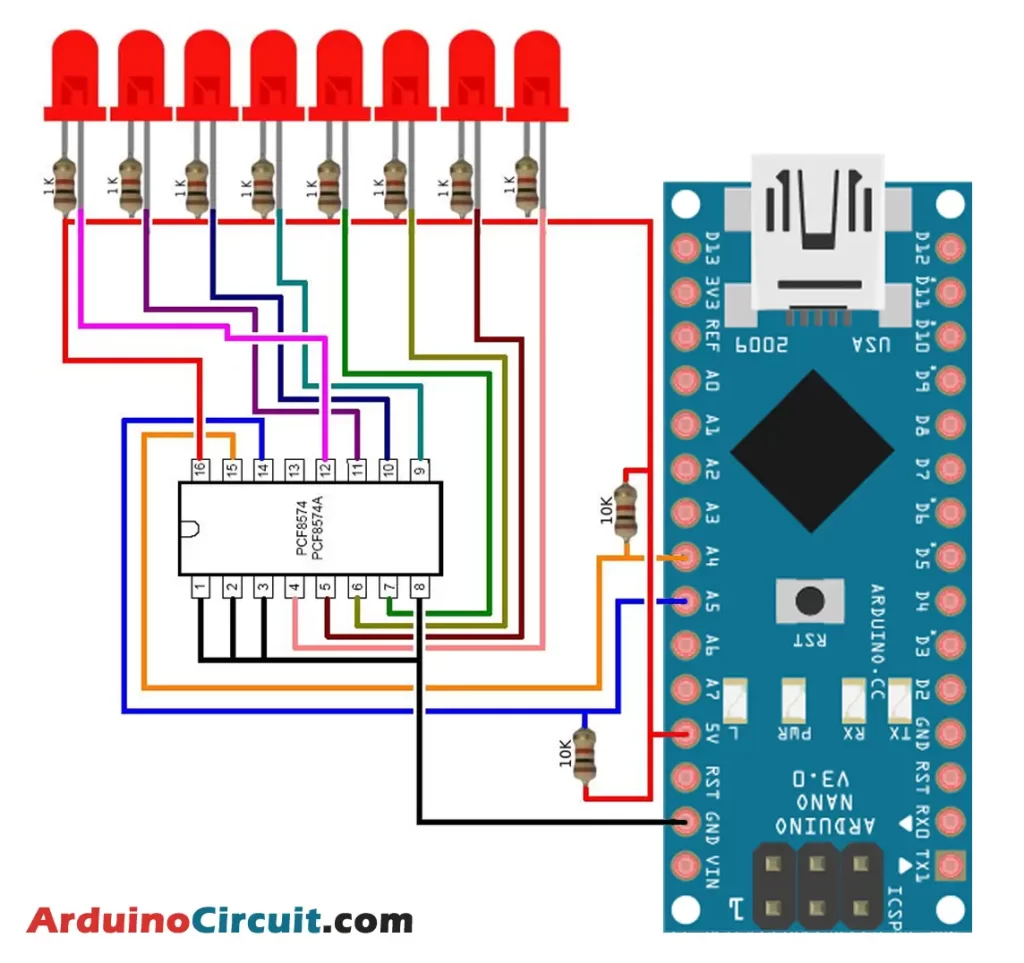
In this project, we will learn how to make LED with PCF8574 – Arduino Project, So the use of the PCF8574 to drive 8 LEDs with the Arduino Nano. The PCF8574 is an 8-bit input/output (I/O) expander for the I2C bus. It allows us to expand the number of I/O pins available on the Arduino board, which is useful when we run out of pins.
Click here For more information About LED with PCF8574 – Arduino Projects and this is the 7th Project of the Top 10 Arduino LED Projects for Beginners with code
Hardware Required
| Components | # | Buy From Amazon |
|---|---|---|
| Arduino Nano | 1 | Buy Now |
| PCF8574 Board | 1 | Buy Now |
| Red LED 5mm | 8 | Buy Now |
| Resistors 1K | 8 | Buy Now |
| Resistors 10K | 1 | Buy Now |
| Jumper Wires | Few | Buy Now |
| Breadboard | 1 | Buy Now |
Circuit Diagram
Code
//For more Projects: www.arduinocircuit.com

#include “Arduino.h”
#include “PCF8574.h”
#include <Wire.h>
// Set i2c address
PCF8574 pcf8574(0x38);

void setup()
{
Serial.begin(9600);

// Set pinMode to OUTPUT
pcf8574.pinMode(P0, OUTPUT);
pcf8574.pinMode(P1, OUTPUT);
pcf8574.pinMode(P2, OUTPUT);
pcf8574.pinMode(P3, OUTPUT);
pcf8574.pinMode(P4, OUTPUT);
pcf8574.pinMode(P5, OUTPUT);
pcf8574.pinMode(P6, OUTPUT);
pcf8574.pinMode(P7, OUTPUT);

pcf8574.begin();
}

void loop()
{
pcf8574.digitalWrite(P0, HIGH);
pcf8574.digitalWrite(P1, LOW);
delay(500);
pcf8574.digitalWrite(P1, HIGH);
pcf8574.digitalWrite(P2, LOW);
delay(500);
pcf8574.digitalWrite(P2, HIGH);
pcf8574.digitalWrite(P3, LOW);
delay(500);
pcf8574.digitalWrite(P3, HIGH);
pcf8574.digitalWrite(P4, LOW);
delay(500);
pcf8574.digitalWrite(P4, HIGH);
pcf8574.digitalWrite(P5, LOW);
delay(500);
pcf8574.digitalWrite(P5, HIGH);
pcf8574.digitalWrite(P6, LOW);
delay(500);
pcf8574.digitalWrite(P6, HIGH);
pcf8574.digitalWrite(P7, LOW);
delay(500);
pcf8574.digitalWrite(P7, HIGH);
pcf8574.digitalWrite(P0, LOW);
delay(500);
}
8: Change Frequency of Blinking LED with Arduino
Introduction
In this tutorial, we will learn how to Change the Frequency of a Blinking LED with Arduino using two buttons. With the help of one button, we will increase the blinking frequency, while the other button will decrease the frequency of the LED blinking.
This project is perfect for beginners who are looking to learn more about basic electronics and programming. It is also a great way to experiment with LEDs and create unique visual effects for your projects. So let’s get started and learn how to change the frequency of a blinking LED with two buttons!
Click here For more information About Change Frequency of Blinking LED with Arduino and this is the 8th Project of the Top 10 Arduino LED Projects for Beginners with code
Hardware Required
| Components | # | Buy From Amazon |
|---|---|---|
| Arduino UNO | 1 | Buy Now |
| LED 5mm | 1 | Buy Now |
| Buttons | 2 | Buy Now |
| Resistors 220Ω | 1 | Buy Now |
| Resistors 10KΩ | 2 | Buy Now |
| Jumper Wires | Few | Buy Now |
| Breadboard | 1 | Buy Now |
Circuit Diagram

Code
//For more Projects: www.arduinocircuit.com

const int ledPin = 9;
const int buttonPin1 = 12; // increase the counter
const int buttonPin2 = 13; // Decrease the counter

int lastState1 = HIGH; // the previous state from the input pin
int lastState2 = HIGH;
int currentState1, currentState2;     // the current reading from the input pin
int pushCounter = 0;  // counter for the number of button presses
int delay_t = 100;
int ledState = LOW;

void setup() {
  pinMode(ledPin, OUTPUT);
  pinMode(buttonPin1, INPUT);
  pinMode(buttonPin2, INPUT);
}

void loop() {
  currentState1 = digitalRead(buttonPin1);
  currentState2 = digitalRead(buttonPin2);
  if (currentState1 != lastState1) {
    if (currentState1 == LOW) {
      pushCounter++;
    }
  }
  lastState1 = currentState1;

  if (currentState2 != lastState2) {
    if (currentState2 == LOW) {
      pushCounter--;
    }
  }

  delay_t = 100 + pushCounter * 100;
  blink_without_delay(delay_t);

  lastState2 = currentState2;
  if (pushCounter >= 10) {
    pushCounter = 0;
  }
  else if (pushCounter < 0) {
    pushCounter = 0;
  }
  delay(50);
}

unsigned long previousMillis = 0; // will store last time LED was updated
void blink_without_delay(long interval) {
  unsigned long currentMillis = millis();
  if (currentMillis - previousMillis >= interval) {
    ledState = !ledState;
    digitalWrite(ledPin, ledState);
    previousMillis = currentMillis;
  }
}
9: RGB LED Indicator To Distance By VL53L0X
Introduction
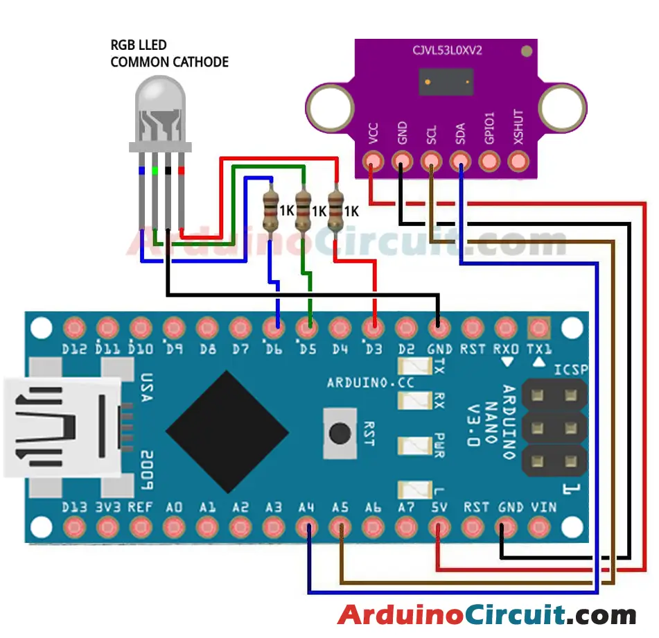
In this project, we will Learn How to make Rgb Led Indicator To Distance By VL53L0X, so basically the RGB LED to indicate the distance measured by VL53L0X time-of-flight sensor. The RGB LED will change its color according to the distance measured by the sensor. The closer the obstacle, the more intense the color will be.
Click here For more information About RGB LED Indicator To Distance By VL53L0X and this is the 9th Project of the Top 10 Arduino LED Projects for Beginners with code
Hardware Required
| Components | # | Buy From Amazon |
|---|---|---|
| Arduino Nano | 1 | Buy Now |
| VL53L0X Distance Sensor | 1 | Buy Now |
| RGB LED (cathode) | 1 | Buy Now |
| Resistor 1K | 3 | Buy Now |
| Jumper Wires | Few | Buy Now |
| Breadboard | 1 | Buy Now |
Circuit Diagram
Code
//For more Projects: www.arduinocircuit.com

const int ledPinRed = 3; // Red LED connected to analogue out pin
const int ledPinGrn = 5; // Green LED connected to analogue out pin
const int ledPinBlu = 6; // Blue LED connected to analogue out pin
// Constants to define the ranges.

const int hueRedLow = 0;
const int hueRedHigh = 255;
const int hueBlue = 170;
const int angleMin = 0;
const int angleSector = 1;
const int angleMax = 360;

const int brightMin = 0;
const int brightMax = 255;

int potValueHue;

int hue, brightness;

const int saturation = 255;
unsigned int r, g, b;
#include <Wire.h>
#include <VL53L0X.h>

VL53L0X sensor;
void setup() {
// Still need to set a baud rate, even for USB.
Serial.begin(9600);
Wire.begin();

sensor.init();
sensor.setTimeout(100);

// Set LED pins to output.
pinMode(ledPinRed, OUTPUT);
pinMode(ledPinGrn, OUTPUT);
pinMode(ledPinBlu, OUTPUT);

sensor.startContinuous();
}

void loop() {
potValueHue = map(sensor.readRangeContinuousMillimeters(), 1000, 0, 0, 360);

hue = constrain(map(potValueHue, angleSector, angleMax – angleSector, hueRedLow, hueBlue), hueRedLow, hueBlue);
brightness = constrain(map(potValueHue, angleMin, angleSector, brightMin, brightMax), brightMin, brightMax);

brightness = brightness – constrain(map(potValueHue, angleMax – angleSector, angleMax, brightMin, brightMax), brightMin, brightMax);

// Do the conversion.
HSBToRGB(hue, saturation, brightness, &r, &g, &b);

analogWrite(ledPinRed, r);
analogWrite(ledPinGrn, g);
analogWrite(ledPinBlu, b);

Serial.print(” bright=”);
Serial.print(brightness);
Serial.print(” hue=”);
Serial.print(hue);
Serial.print(” red=”);
Serial.print(r);
Serial.print(” green=”);
Serial.print(g);
Serial.print(” blue=”);
Serial.print(b);
Serial.println(“”);
delay(50);
}

void HSBToRGB(
unsigned int inHue, unsigned int inSaturation, unsigned int inBrightness,
unsigned int *oR, unsigned int *oG, unsigned int *oB )
{
if (inSaturation == 0)
{
// achromatic (grey)
*oR = *oG = *oB = inBrightness;
}
else
{
unsigned int scaledHue = (inHue * 6);
unsigned int sector = scaledHue >> 8; // sector 0 to 5 around the color wheel
unsigned int offsetInSector = scaledHue – (sector << 8); // position within the sector
unsigned int p = (inBrightness * ( 255 – inSaturation )) >> 8;
unsigned int q = (inBrightness * ( 255 – ((inSaturation * offsetInSector) >> 8) )) >> 8;
unsigned int t = (inBrightness * ( 255 – ((inSaturation * ( 255 – offsetInSector )) >> 8) )) >> 8;
switch( sector ) {
case 0:
*oR = inBrightness;
*oG = t;
*oB = p;
break;
case 1:
*oR = q;
*oG = inBrightness;
*oB = p;
break;
case 2:
*oR = p;
*oG = inBrightness;
*oB = t;
break;
case 3:
*oR = p;
*oG = q;
*oB = inBrightness;
break;
case 4:
*oR = t;
*oG = p;
*oB = inBrightness;
break;
default: // case 5:
*oR = inBrightness;
*oG = p;
*oB = q;
break;
}
}
}
10: Arduino Push Button with Multiple LEDs Tutorial
Introduction
This tutorial demonstrates how to use an Arduino Push Button with Multiple LEDs. The push button will toggle the LEDs on and off in a specific sequence. This is a great introduction to basic programming concepts and can be easily modified to create more complex LED sequences.
Push buttons are a commonly used component in electronics projects, allowing for user input and control of various functions. In this tutorial, we will use a push button to control multiple LEDs, creating a simple but effective display. By wiring the LEDs to the Arduino board and programming the board to respond to button presses, we can easily switch between the different LEDs and create a visually appealing effect. This tutorial is a great introduction to working with buttons and LEDs in Arduino projects and can be easily adapted for more complex projects. So, let’s get started and learn how to control multiple LEDs with a push button!
Click here For more information About Arduino the Push Button with Multiple LEDs Tutorial, this is the 10th Project of the Top 10 Arduino LED Projects for Beginners with code
Hardware Required
| Components | # | Buy From Amazon |
|---|---|---|
| Arduino UNO | 1 | Buy Now |
| Push Button | 1 | Buy Now |
| LEDs (Different Color) | 4 | Buy Now |
| Resistors 220Ω | 4 | Buy Now |
| Resistors 10KΩ | 1 | Buy Now |
| Jumper Wires | Few | Buy Now |
| Breadboard | 1 | Buy Now |
Circuit Diagram

Code
//For more Projects: www.arduinocircuit.com

int ledPin[4] = {8, 9, 10, 11};

const int buttonPin = 13;
int buttonState = HIGH;
int pushCounter = 0;
int numberOfLED = 4;
void setup() {
  pinMode(buttonPin, INPUT);
  for (int i = 0; i <= 4; i++) {
    pinMode(ledPin[i], OUTPUT);
  }
}

void loop() {
  buttonState = digitalRead(buttonPin);
  if (buttonState == LOW) {
    for (int i = 0; i < numberOfLED; i++) {
      if (pushCounter % numberOfLED == i) {
        digitalWrite(ledPin[i], HIGH);
      }
      else {
        digitalWrite(ledPin[i], LOW);
      }
    }
    pushCounter++;
    delay(400);
  }
}
Conclusion
Working on Arduino LED projects is a great way for beginners to dive into the world of electronics and programming. These projects provide hands-on experience in working with LEDs, understanding basic circuit connections, and coding using the Arduino platform. By following the code examples and instructions provided, beginners can gradually enhance their skills and creativity in designing their own LED projects. Whether it’s blinking LEDs, controlling LED brightness, or creating dynamic lighting effects, these projects offer a solid foundation for anyone interested in learning Arduino and exploring the possibilities of LED-based projects. So grab your Arduino board, gather your components, and get ready to embark on an exciting journey of Arduino LED projects!


