
Introduction
In this Arduino tutorial, we will explore Arduino RGB LED | Arduino Tutorial, and how to control an RGB LED using an Arduino UNO board. RGB LEDs are versatile light-emitting diodes that can produce a wide range of colors by combining red, green, and blue light. By connecting an RGB LED to an Arduino board, we can create stunning lighting effects and add visual appeal to our projects. Let’s dive into the required components and the steps involved in setting up and controlling an RGB LED with Arduino.
Hardware Required
To get started with the Arduino RGB LED | Arduino Tutorial, you will need the following components
| Components | # | Buy From Amazon |
|---|---|---|
| Arduino UNO | 1 | Buy Now |
| RGB LED | 1 | Buy Now |
| RGB LED Module | 1 | Buy Now |
| Resistor 220Ω | 3 | Buy Now |
| Jumper Wires | 4 | Buy Now |
| Breadboard | 1 | Buy Now |
| 9v DC Adapter (Optional) | 1 | Buy Now |
What is an LED?
The RGB LED module with an Arduino UNO board. RGB LED modules are convenient components that integrate the RGB LED, resistors, and control circuitry into a single module. They allow for easy control of color and lighting effects in Arduino projects.
Pinout

Pin Configuration
| Pin Name | Pin Type |
|---|---|
| R | Red Pin |
| G | Green Pin |
| B | Blue Pin |
| Common | (Cathode -) Pin connected to GND |
Pinout
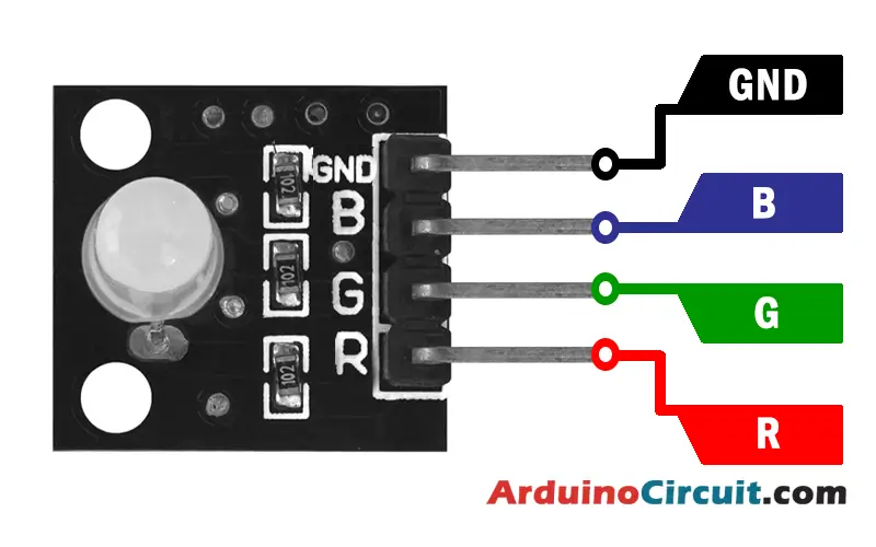
Pin Configuration
| Pin Name | Pin Type |
|---|---|
| B | Blue Pin |
| G | Green Pin |
| R | Red Pin |
| ( – ) GND | Ground Pin |
Specifications
- Input Voltage: The RGB LED module typically operates at 5V, which is compatible with the Arduino UNO board.
- LED Type: The module consists of a common cathode RGB LED, which has separate pins for the red, green, and blue colors.
- Current Limiting Resistors: The module is equipped with built-in current limiting resistors for each color, ensuring safe operation.
- Control Pins: The module has three control pins, one for each color component, allowing individual control of the RGB LED.
Features
- Easy Integration: The module simplifies the connection and control of the RGB LED by integrating the necessary components into a single module.
- Bright and Vibrant Colors: The RGB LED module can produce a wide range of colors by varying the intensity of the red, green, and blue components.
- Compact Design: The module’s compact size makes it suitable for projects with limited space or when a neat and organized setup is desired.
- Simplified Wiring: With the built-in resistors and control circuitry, the module reduces the number of external components required and simplifies the wiring process.
- Compatible with Arduino: The module is designed to work seamlessly with the Arduino UNO board, making it accessible to Arduino enthusiasts and beginners.
Circuit Connections
To set up the circuit for the Arduino RGB LED project, follow these steps:
- Connect the longer leg (anode) of the RGB LED to Arduino’s digital pins. Assign each leg to a different pin: red to pin 9, green to pin 10, and blue to pin 11.
- Connect the shorter leg (cathode) of the RGB LED to a current-limiting resistor (e.g., 220 ohms). Then, connect the other end of the resistor to the Arduino’s ground (GND) pin.
- Ensure that all the components are properly seated on the breadboard and securely connected with jumper wires.
Circuit Diagram
Connection diagram between Arduino and RGB LED.

Circuit Diagram
Connection diagram between Arduino and RGB LED module.

Working Principle of RGB LED
The RGB LED module operates by adjusting the intensity of each color component. By varying the voltage applied to the red, green, and blue pins, we can control the brightness of each color. The combination of different intensities produces various colors. The Arduino board sends control signals to the module’s control pins, instructing it to display specific colors or lighting effects.
Installing Arduino IDE Software
First, you will require to Download the updated version of Arduino IDE Software and Install it on your PC or laptop. if you Learn How to install the Arduino step-by-step guide then click on how to install Arduino Button given Blow
Code
The below code changes the color of the LED between the following colors in sequence:
- #00C9CC (R = 0, G = 201, B = 204)
- #F7788A (R = 247, G = 120, B = 138)
- #34A853 (R = 52, G = 168, B = 83)
//For more Projects visit at: www.arduinocircuit.com


const int PIN_RED   = 5;
const int PIN_GREEN = 6;
const int PIN_BLUE  = 9;

void setup() {
  pinMode(PIN_RED,   OUTPUT);
  pinMode(PIN_GREEN, OUTPUT);
  pinMode(PIN_BLUE,  OUTPUT);
}

void loop() {
  // color code #00C9CC (R = 0,   G = 201, B = 204)
  analogWrite(PIN_RED,   0);
  analogWrite(PIN_GREEN, 201);
  analogWrite(PIN_BLUE,  204);

  delay(1000); // keep the color 1 second

  // color code #F7788A (R = 247, G = 120, B = 138)
  analogWrite(PIN_RED,   247);
  analogWrite(PIN_GREEN, 120);
  analogWrite(PIN_BLUE,  138);

  delay(1000); // keep the color 1 second

  // color code #34A853 (R = 52,  G = 168, B = 83)
  analogWrite(PIN_RED,   52);
  analogWrite(PIN_GREEN, 168);
  analogWrite(PIN_BLUE,  83);

  delay(1000); // keep the color 1 second
}
Adding More Tasks
The below code blinks two LEDs with various intervals and checks the state of the button.
Code
When utilizing many colors, we could shorten the code by creating a function
//For more Projects visit at: www.arduinocircuit.com


const int PIN_RED   = 5;
const int PIN_GREEN = 6;
const int PIN_BLUE  = 9;

void setup() {
  pinMode(PIN_RED,   OUTPUT);
  pinMode(PIN_GREEN, OUTPUT);
  pinMode(PIN_BLUE,  OUTPUT);
}

void loop() {
  // color code #00C9CC (R = 0,   G = 201, B = 204)
  setColor(0, 201, 204);

  delay(1000); // keep the color 1 second

  // color code #F7788A (R = 247, G = 120, B = 138)
  setColor(247, 120, 138);

  delay(1000); // keep the color 1 second

  // color code #34A853 (R = 52,  G = 168, B = 83)
  setColor(52, 168, 83);

  delay(1000); // keep the color 1 second
}

void setColor(int R, int G, int B) {
  analogWrite(PIN_RED,   R);
  analogWrite(PIN_GREEN, G);
  analogWrite(PIN_BLUE,  B);
}
Code Explanation
The code for controlling the RGB LED with Arduino involves adjusting the intensity of each color component. Here’s an overview of the code structure:
- Variable Declaration: Declare variables to store the pin numbers for the RGB LED’s red, green, and blue pins.
- Initialization: In the setup() function, set the designated pins as outputs using the pinMode() function.
- Main Loop: In the loop() function, use the analogWrite() function to control the intensity of each color component. By adjusting the values between 0 and 255, you can create different colors and lighting effects.
- Color Combinations: Experiment with different combinations of red, green, and blue intensities to create a variety of colors. By varying the intensity of each color, you can achieve unique lighting patterns and ambiance.
Applications
- Mood Lighting: The RGB LED module is perfect for creating ambient lighting and mood-enhancing effects in home decor projects.
- Display Panels: It can be used to create colorful displays, signage, or visual indicators where vibrant colors are required.
- Interactive Projects: The module is ideal for interactive projects such as color-changing gaming consoles, visual feedback systems, or interactive art installations.
- Robotics and IoT: In robotics and IoT projects, the RGB LED module can be used to indicate status, provide visual feedback, or enhance the aesthetics of the project.
- Educational Purposes: The RGB LED module is a great tool for teaching electronics, programming, and Arduino concepts to beginners due to its simplicity and versatility.
Conclusion
In this Arduino tutorial, we explored the RGB LED module and its applications. We discussed its specifications, features, and working principle, and highlighted its versatility and ease of use. The RGB LED module offers an accessible way to incorporate dynamic lighting effects into Arduino projects, allowing for creative expression and enhanced project aesthetics. With its compact design, simplified wiring, and compatibility with Arduino, the RGB LED module is an excellent choice for beginners and experienced enthusiasts alike. So go ahead, unleash your creativity, and bring vibrant colors to your Arduino projects with the RGB LED module.


