Introduction
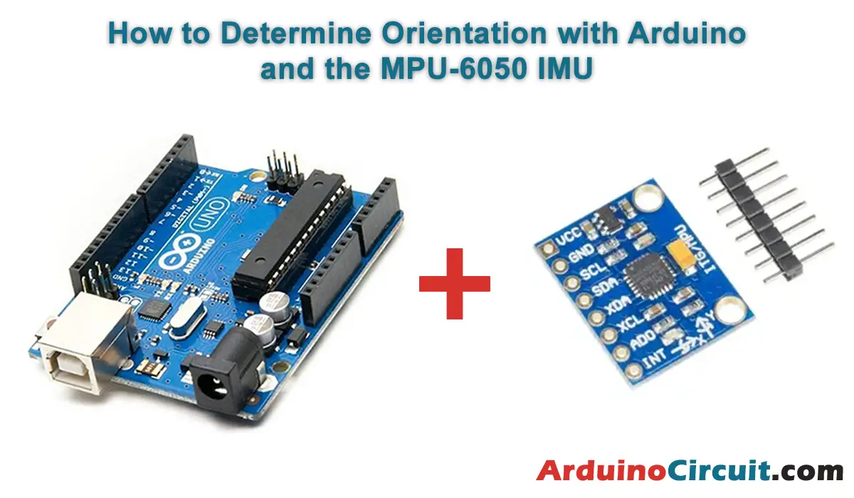
Welcome to the exciting world of Arduino and motion sensing! In this guide, we’ll explore How to Determine Orientation with Arduino and the MPU-6050 IMU Inertial Measurement Unit (IMU). The MPU-6050 IMU is a versatile sensor module that provides accurate measurement of orientation, acceleration, and gyroscopic motion. Let’s delve into the details of the MPU-6050 IMU and learn how to leverage its capabilities with Arduino to determine orientation in your projects.
Hardware Required
You will require the following Hardware Components for the How to Interface MPU6050 Accelerometer & Gyroscope Module Sensor with Arduino.
| Components | # | Buy From Amazon |
|---|---|---|
| Arduino UNO | 1 | Buy Link |
| MPU6050 Sensor | 1 | Buy Now |
| 9v DC Adapter (Optional) | 1 | Buy Link |
| Jumper Wires | 4 | Buy Link |
| Breadboard | 1 | Buy Link |
What is an MPU-6050 IMU?
The MPU-6050 is a 6DOF IMU produced by Invensense, merging a 3-axis accelerometer and a 3-axis gyroscope. It communicates via SPI or I2C, facilitating data retrieval with a low voltage supply of 2.4 to 3.6V.
Commonly found in modules like the GY-521, it integrates a voltage regulator for direct 5V input. Featuring 16-bit ADCs, it offers selectable ranges for the accelerometer (±2g to ±16g) and gyroscope (±250°/sec to ±2000°/sec).
Consuming 3.5mA, it includes features like an embedded temperature sensor, precise clock, and programmable interrupts. It can also serve as a master to connect with other I2C devices.
The MPU-6050 houses an internal DMP that executes complex MotionFusion algorithms, eliminating the need for external filters. Renowned for its quality and affordability, it’s a go-to component for electronics and robotics projects.
Pinout

MPU6050 Pinout Configuration
| Pin Name | Description |
|---|---|
| Vcc | Provides power for the module, can be +3V to +5V. Typically +5V is used |
| Ground | Connected to Ground of system |
| (SCL) Serial Clock | Used for providing clock pulse for I2C Communication |
| (SDA) Serial Data | Used for transferring Data through I2C communication |
| (XDA) Auxiliary Serial Data | Can be used to interface other I2C modules with MPU6050. It is optional |
| (XCL) Auxiliary Serial Clock | Can be used to interface other I2C modules with MPU6050. It is optional |
| AD0 | If more than one MPU6050 is used a single MCU, then this pin can be used to vary the address |
| (INT) Interrupt | Interrupt pin to indicate that data is available for MCU to read. |
Features
- 6-Axis Motion Sensing: Combines accelerometer and gyroscope sensors to provide comprehensive motion sensing capabilities.
- Digital Motion Processing: Onboard Digital Motion Processor (DMP) offloads computation from the Arduino, allowing for efficient motion processing.
- Low Power Consumption: Designed for low power operation, making it suitable for battery-powered applications.
- High Precision: High-resolution sensors ensure accurate measurement of motion and orientation.
- Motion Interrupts: Supports motion detection interrupts, allowing Arduino to wake up from sleep mode when motion is detected.
Specifications
- Accelerometer:
- Range: ±2g, ±4g, ±8g, ±16g selectable.
- Resolution: 16-bit.
- Gyroscope:
- Range: ±250, ±500, ±1000, ±2000 degrees per second (dps) selectable.
- Resolution: 16-bit.
- Communication Interface:
- I2C (Inter-Integrated Circuit) interface for communication with Arduino.
- Operating voltage: 3.3V.
- Dimensions:
- Small form factor suitable for integration into various electronic projects.
- Typical breakout board design for easy connection with Arduino.
- Sampling Rate:
- Accelerometer and gyroscope data can be sampled at rates up to 1kHz.
Circuit Diagram
The following circuit shows you the connection of the How to Determine Orientation with Arduino and the MPU-6050 IMU, Please make the connection carefully

Circuit Connections
| Arduino | MPU6050 Sensor |
|---|---|
| +5V | VCC Pin |
| GND | GND Pin |
| A4 | SDA |
| A5 | SCL |
Installing Arduino IDE Software
First, you will require to Download the updated version of Arduino IDE Software and Install it on your PC or laptop. if you Learn How to install the Arduino step-by-step guide then click on how to install Arduino Button given Blow
Installing Libraries
Now when you are Ready to upload the code, to the Arduino Board you will need first to add the Following Libraries in Arduino, If you Learn How to add the library in the Arduino step-by-step guide click on how to install the library Button given Blow
Code Examples
Read RAW values:
In this First example, we’ll demonstrate how to directly read the values provided by the MPU-6050 (RAW values) via the I2C bus. RAW values have a measurement range spanning from -32768 to +32767.
//For more Projects: www.arduinocircuit.com
//GND - GND
//VCC - VCC
//SDA - Pin A4
//SCL - Pin A5
#include "I2Cdev.h"
#include "MPU6050.h"
#include "Wire.h"
const int mpuAddress = 0x68; //Can be 0x68 or 0x69
MPU6050 mpu(mpuAddress);
int ax, ay, az;
int gx, gy, gz;
void printTab()
{
Serial.print(F("\t"));
}
void printRAW()
{
Serial.print(F("a[x y z] g[x y z]:t"));
Serial.print(ax); printTab();
Serial.print(ay); printTab();
Serial.print(az); printTab();
Serial.print(gx); printTab();
Serial.print(gy); printTab();
Serial.println(gz);
}
void setup()
{
Serial.begin(9600);
Wire.begin();
mpu.initialize();
Serial.println(mpu.testConnection() ? F("IMU started successfully") : F("Error starting IMU"));
}
void loop()
{
// Read accelerations and angular velocities
mpu.getAcceleration(&ax, &ay, &az);
mpu.getRotation(&gx, &gy, &gz);
printRAW();
delay(100);
}Read values in International System:
In the following example, we’ll demonstrate how to apply scaling to the RAW values obtained from the MPU-6050 to derive measurements with physical units. Specifically, we’ll convert the values to G for acceleration and degrees per second (°/s) for angular velocity. It’s worth noting that you can easily modify the code to provide values in units of the International System.
The scaling process will depend on the measurement range selected in the MPU-6050, which includes options such as 2g/4g/8g/16g for the accelerometer and 250/500/1000/2000 (°/s) for the gyroscope.
//For more Projects: www.arduinocircuit.com
//GND - GND
//VCC - VCC
//SDA - Pin A4
//SCL - Pin A5
#include "I2Cdev.h"
#include "MPU6050.h"
#include "Wire.h"
const int mpuAddress = 0x68; // Can be 0x68 or 0x69
MPU6050 mpu(mpuAddress);
int ax, ay, az;
int gx, gy, gz;
// Conversion factors
const float accScale = 2.0 * 9.81 / 32768.0;
const float gyroScale = 250.0 / 32768.0;
void printTab()
{
Serial.print(F("\t"));
}
// Show measurements in International System
void printRAW()
{
Serial.print(F("a[x y z](m/s2) g[x y z](deg/s):t"));
Serial.print(ax * accScale); printTab();
Serial.print(ay * accScale); printTab();
Serial.print(az * accScale); printTab();
Serial.print(gx * gyroScale); printTab();
Serial.print(gy * gyroScale); printTab();
Serial.println(gz * gyroScale);
}
void setup()
{
Serial.begin(9600);
Wire.begin();
mpu.initialize();
Serial.println(mpu.testConnection() ? F("IMU started successfully") : F("Error starting IMU"));
}
void loop()
{
// Read accelerations and angular velocities
mpu.getAcceleration(&ax, &ay, &az);
mpu.getRotation(&gx, &gy, &gz);
printRAW();
delay(100);
}Read inclination with accelerometer:
In the following example, we determine the tilt of the MPU-6050 by utilizing trigonometric relationships to project the gravity measurement, as discussed in the “How to use an accelerometer with Arduino” entry.
//For more Projects: www.arduinocircuit.com
//GND - GND
//VCC - VCC
//SDA - Pin A4
//SCL - Pin A5
#include "I2Cdev.h"
#include "MPU6050.h"
#include "Wire.h"
const int mpuAddress = 0x68; // Can be 0x68 or 0x69
MPU6050 mpu(mpuAddress);
int ax, ay, az;
int gx, gy, gz;
void setup()
{
Serial.begin(9600);
Wire.begin();
mpu.initialize();
Serial.println(mpu.testConnection() ? F("IMU started successfully") : F("Error starting IMU"));
}
void loop()
{
// Read accelerations
mpu.getAcceleration(&ax, &ay, &az);
//Calculate the angles of inclination
float accel_ang_x = atan(ax / sqrt(pow(ay, 2) + pow(az, 2)))*(180.0 / 3.14);
float accel_ang_y = atan(ay / sqrt(pow(ax, 2) + pow(az, 2)))*(180.0 / 3.14);
// Show results
Serial.print(F("Inclination in X: "));
Serial.print(accel_ang_x);
Serial.print(F("\tY Tilt:"));
Serial.println(accel_ang_y);
delay(10);
}Get guidance with gyroscope:
In the following example, we integrate the gyroscope speed signal to derive the orientation of the MPU-6050, as demonstrated in the “How to use a gyroscope with Arduino” entry.
//For more Projects: www.arduinocircuit.com
//GND - GND
//VCC - VCC
//SDA - Pin A4
//SCL - Pin A5
#include "I2Cdev.h"
#include "MPU6050.h"
#include "Wire.h"
const int mpuAddress = 0x68; // Can be 0x68 or 0x69
MPU6050 mpu(mpuAddress);
int ax, ay, az;
int gx, gy, gz;
long prev_time, dt;
float gyrosc_ang_x, gyrosc_ang_y;
float gyrosc_ang_x_prev, gyrosc_ang_y_prev;
void updateSpin()
{
dt = millis() - previous_time;
previous_time = millis();
gyrosc_ang_x = (gx / 131)*dt / 1000.0 + gyrosc_ang_x_prev;
gyrosc_ang_y = (gy / 131)*dt / 1000.0 + gyrosc_ang_y_prev;
gyrosc_ang_x_prev = gyrosc_ang_x;
gyrosc_ang_y_prev = gyrosc_ang_y;
}
void setup()
{
Serial.begin(9600);
Wire.begin();
mpu.initialize();
Serial.println(mpu.testConnection() ? F("IMU started successfully") : F("Error starting IMU"));
}
void loop()
{
// Read angular velocities
mpu.getRotation(&gx, &gy, &gz);
updateSpin();
// Show results
Serial.print(F("Rotation in X: "));
Serial.print(turnsc_ang_x);
Serial.print(F("\tRotation in Y: "));
Serial.println(girosc_ang_y);
delay(10);
}Applications
- Robotics: Use the MPU-6050 IMU to track the orientation and motion of robotic systems, enabling precise control and navigation.
- Gesture Recognition: Implement gesture recognition systems using MPU-6050 to detect and recognize hand gestures for human-computer interaction.
- Stabilization Systems: Integrate MPU-6050 into stabilization systems for cameras, drones, and other devices to maintain stable orientation and reduce vibrations.
- Gaming Devices: Incorporate MPU-6050 into gaming controllers and devices to detect motion and orientation changes for immersive gaming experiences.
- Inertial Navigation: Utilize MPU-6050 in navigation systems for dead reckoning and inertial navigation, providing position and orientation estimation in GPS-denied environments.
Conclusion
With its advanced capabilities and versatility, the MPU-6050 IMU offers endless possibilities for motion sensing and orientation tracking in Arduino projects. Whether you’re building robots, gesture-controlled interfaces, stabilization systems, gaming devices, or navigation systems, the MPU-6050 provides accurate and reliable motion data for enhanced functionality and performance. Let’s get started with using MPU-6050 IMU with Arduino and unlock the potential of motion sensing in your projects!


